Defining Composite Outlet Structures
CivilStorm lets you define composite outlet structures for pond outlet structures in your model. A composite outlet structure can contain any combination of orifices, risers, and weirs. You define these outlet structures in the Composite Outlet Structures dialog box.
To define a composite outlet structure:
- Click a pond outlet structure in your model to display the Property Editor, or right-click a pond outlet structure and select Properties from the shortcut menu.
- In the Pond Outlet section of the Property Editor, select Yes in the Has Control Structure field. The Control Structure field becomes available.
- Click the Ellipses (...) button next to the Control Structure field. The Composite Outlet Structures dialog box appears, displaying the existing composite outlet structure associated with the selected pond outlet structure.
- To create a new composite outlet structure, perform these steps:
- Click New, then select the type of outlet structure component you want to add. The right side of the dialog box displays settings for the composite outlet structure and for each individual component in the composite outlet structure. With the composite outlet structure selected in the list pane, enter values for Tolerance Settings and ICPM Settings. Select each individual component in the list pane, then enter values for that component in the fields on the right. If you define a weir as an Irregular Weir, you must define the cross-sectional shape of the irregular weir by entering X (Station) vs. Y (Depth) data. To do this, click the Cross Section button, enter X and Y values in the Irregular Cross Section dialog box, then click OK to close that dialog box.
- To edit an existing composite outlet structure, perform these steps:
- If necessary, edit the Tolerance Settings and ICPM Settings for the selected composite outlet structure. Click the plus sign (+) next to the outlet structure in the list pane to display its individual components. Select the component (Orifice, Riser, or Weir), then edit the values for the component on the right side of the dialog box. If you define a weir as an Irregular Weir, you must define the cross-sectional shape of the irregular weir by entering X (Station) vs. Y (Depth) data. To do this, click the Cross Section button, enter X and Y values in the Irregular Cross Section dialog box, then click OK to close that dialog box. To add a new component to an existing composite outlet structure, select the outlet structure in the list pane then click New and select Orifice, Riser, or Weir from the submenu. You can also right click an existing composite structure in the list pane, then select New > Orifice, New > Riser, or New > Weir from the shortcut menu.
- Perform the following optional steps:
- To delete a row from the table, select the row then click Delete.
- To rename an existing composite outlet structure, click Rename, then type the new name.
- To view a report on the composite outlet structure, click Report.
- To view a plot of the composite outlet structure, click Graph. The graph will display multiple curves, one for each component in the composite outlet structure.
- Click OK to close the dialog box and save your data in the Property Editor.
Composite Outlet Structures Dialog Box
The Composite Outlet Structures dialog lets you create complex outlet structures.
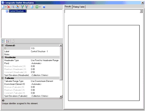
The dialog consists of a tree view pane and property editor on the left and a tabbed section on the right. The tree view displays all of the outlet structure definitions associated with the model. The property editor allows you to define the attributes of the element currently highlighted in the tree view. Above the tree view are the following buttons:

New: Creates a new entry in the list pane.
Delete: Removes the entry that is currently highlighted in the list pane
Rename: Allows you to enter a new label for the entry that is currently highlighted in the list pane.
Duplicate: Creates a copy of the entry that is currently highlighted in the list pane.
Expand All: Expands each of the nodes in the tree view, so that all entries are displayed.
Collapse All: Collapses each of the nodes so that only the top-level nodes are visible.
Report: Generates a preformatted report that details the data associated with the entry that is currently highlighted in the list pane.
Compute: When you click this button a submenu opens. The submenu contains the following commands:- Validate: Click this button to perform a validation on the entry that is currently highlighted in the list pane.
- Compute: Click this button to compute the entry that is currently highlighted in the list pane.
- Compute All: Click this button to compute all of the entries in the list pane.

Help: Opens the online help associated with this dialog.
The attributes displayed in the property editor section below the tree view will change depending on the type of node that is currently highlighted in the tree view. Depending on the node type, the property grid allows you to define the following attributes:
- Composite Structure Node (Top Level Node): When a top level node is highlighted in the tree view, the following properties are available:
- ID: Unique identifier assigned to this element.
- Label: Descriptive label for this element.
- Notes: Additional information about this element.
- Headwater Type: The type of headwater range to use.
- Pond: The pond to use for headwater range.
The headwater and tailwater elements do not need to be user-defined to determine the ranges. If edited from the Properties grid of the pond outlet structure node the ranges will automatically be determined ( in the same way as if you computed the entire hydraulic model).
- Minimum (Headwater): The minimum pond surface elevation to use in the headwater range.
- Increment (Headwater): The step value represents the step increment for the rating table. As a general rule, interpolation precision between table points increases as the step increment is decreased.
- Maximum (Headwater): The maximum pond surface elevation to use in the headwater range.
- Spot Elevations (Headwater): The spot elevations for the headwater range.
- Tailwater Range Type: Select the type of tailwater range to specify. You can specify a user defined range or automatically determine the range by selecting a pond or outfall.
- Downstream Element ID: Specify the domain element in which to determine the tailwater range or leave it set to Automatic and let the application figure it out automatically.
- Minimum (Tailwater): The minimum tailwater elevation to use in the range.
- Increment (Tailwater): Set the step used to compute the rating curve for the elevation beginning at the minimum tailwater and increment by this tailwater step elevation until the maximum tailwater is reached. In general, smaller tailwater step increments yield more precise routing interpolation.
- Maximum (Tailwater): The maximum tailwater elevation to use in the range.
- Spot Elevations (Tailwater): The spot elevations for the tailwater range.
- Store Elevation-Flow-Tailwater Table: Determines if the elevation-flow-tailwater curves are stored. This option can be used in conjunction with the Store Elevation-Flow-Tailwater Table? Calculation Option. See Store Elevation-Flow-Tailwater Table’ for more details.
- Elevation-Flow-Tailwater Table: The E-Q-TW table to save results to.
- Maximum Iterations: During iterative tailwater convergence procedures, computations will stop after exceeding the specified maximum iterations.
- Headwater Tolerance (Minimum): If CivilStorm is checking computed headwater (HW) elevations during the iterative HW convergence computations, minimum headwater tolerance and maximum headwater tolerance values specify the minimum target convergence and the maximum allowable difference between the computed value and the known headwater value.
- Headwater Tolerance (Maximum): If CivilStorm is checking computed headwater (HW) elevations during the iterative HW convergence computations, minimum headwater tolerance and maximum headwater tolerance values specify the minimum target convergence and the maximum allowable difference between the computed value and the known headwater value.
- Tailwater Tolerance (Minimum): If CivilStorm is checking computed tailwater (TW) elevations during the iterative TW convergence computations, minimum tailwater tolerance and maximum tailwater tolerance values specify the minimum target convergence and the maximum allowable difference between the computed value and the known tailwater value.
- Tailwater Tolerance (Maximum): If CivilStorm is checking computed tailwater (TW) elevations during the iterative TW convergence computations, minimum tailwater tolerance and maximum tailwater tolerance values specify the minimum target convergence and the maximum allowable difference between the computed value and the known tailwater value.
- Flow Tolerance (Minimum): If CivilStorm is checking computed flow during the iterative TW convergence computations, these tolerance values specify the minimum target convergence and the maximum allowable difference between the computed value and the known flow value. Iterative computations on flow are ended when either the solution converges within the minimum flow tolerance, or when more than the specified maximum iterations are performed. In general, smaller flow tolerances yield more precise convergence.
- Flow Tolerance (Maximum): If CivilStorm is checking computed flow during the iterative TW convergence computations, these tolerance values specify the minimum target convergence and the maximum allowable difference between the computed value and the known flow value. Iterative computations on flow are ended when either the solution converges within the minimum flow tolerance, or when more than the specified maximum iterations are performed. In general, smaller flow tolerances yield more precise convergence.
- Orifice Attributes: When an Orifice is selected in the tree view the following attributes are available:
- Elevation: Structure’s invert elevation.
- Outlet ID: Upstream structure ID.
- Flow Direction: Defines the direction in which flow is considered.
- Downstream ID: Downstream Structure ID.
- Notes: Additional information about this element.
- Elevation (On): Elevation (On) is the lower elevation of range over which to use this structure. No flows will be computed for elevations less than this value. If 0.0 then this value is ignored.
- Elevation (Off): Elevation (Off) is the upper elevation of range over which to use this structure. No flows will be computed for elevations equal to or greater than this number. If 0.0 then this value is ignored.
- Orifice: The type of orifice this structure represents.
- Number of Openings: Set the number of openings the orifice uses.
- Orifice Coefficient: The orifice coefficient for this structure.
- Orifice Diameter: The orifice diameter for this structure.
- Orifice Area: The orifice area for this structure.
- Orifice Orientation: The orientation of this orifice structure.
- Datum Elevation: The datum elevation for this orifice structure.
- Top Elevation: The top elevation of this orifice structure.
- Riser Attributes: When a Riser is selected in the tree view the following attributes are available:
- Elevation: Structure’s invert elevation.
- Outlet ID: Upstream structure ID.
- Flow Direction: Defines the direction in which flow is considered.
- Downstream ID: Downstream Structure ID.
- Notes: Additional information about this element.
- Elevation (On): Elevation (On) is the lower elevation of range over which to use this structure. No flows will be computed for elevations less than this value. If 0.0 then this value is ignored.
- Elevation (Off): Elevation (Off) is the upper elevation of range over which to use this structure. No flows will be computed for elevations equal to or greater than this number. If 0.0 then this value is ignored.
- Riser: The type of riser for this structure.
- Diameter: The stand pipe diameter for this structure.
- Weir Coefficient: The
coefficient of discharge multiplied by other constants in the weir flow
equation. For example, flow over a rectangular weir with no end contractions
can be determined using the following equation:

Where:
- Q = discharge (cfs, m3/s)
- Cd = coefficient of discharge
- g = gravitational constant (32.2 ft/s2, 9.81 m/s2)
- L = length of the weir crest (ft, m)
- H = height of the energy grade above weir crest (ft, m)
- In this case the Weir
Coeffcient,

(ft0.5/s, m0.5/s), simplifying the weir equation to:
. - A typical value for the Weir Coefficient is 3.3 (ft0.5/s) or 1.8 (m0.5/s).
- Orifice Coefficient: The orifice coefficient for this structure.
- Orifice Area: The orifice area of this riser structure.
- Transition Elevation: The transition elevation for this structure.
- Transition Height: The transition height for this structure.
- K Reverse: The K reverse coefficient for this structure.
- Weir Length: The weir length of this riser structure.
- Use Orifice Depth to Crest?: There are two methods available to calculate the headwater depth of a fully charged riser orifice. The default method measures the headwater depth from the riser crest to the headwater elevation. The other method measures the headwater depth from the tailwater elevation to the headwater elevation. To use the first method, this value should be set to True (the default). To use the second method, set this property to False.
- If the Use Orifice Depth to Crest property is set to True, then Head Across Orifice = Pond Elevation - Riser Crest Elevation.
- If the Use Orifice Depth to Crest property is set to False, then Head Across Orifice = Pond Elevation - Tailwater Elevation.
- Use Submerged Weir Equation?: There are two methods available to calculate a fully-charged riser weir flow: non-submerged weir and submerged weir. The non-submerged weir method is used when this property is set to False (the default method). When this property is set to True, the submerged weir method is used.
- If the Use Submerged Weir Equation? property is set to False, then:
- Qw = Kwc * Lw * (Pond Elevation - riser crest)1.5
- Where:
- Qw = weir flow through the riser
- Kwc = riser weir flow coefficient
- Lw = riser weir length
- If the Use Submerged Weir Equation? property is set to True, then
- Qws = Qw * (1 - (H2/H1)1.5)0.385
- Where:
- Qw = weir flow through the riser
- Qws = weir flow through riser (weir is submerged)
- H1 = Pond Elevation - Riser Crest Elevation
- H2 = Tailwater Elevation - Riser Crest Elevation
- Culvert Attributes: When a Culvert is selected in the tree view the following attributes are available:
- Culvert Type: The type of culvert.
- Outlet ID: Upstream structure ID.
- Flow Direction: Defines the direction in which flow is considered.
- Downstream ID: Downstream Structure ID.
- Notes: Additional information about this element.
- Convergence Tolerance: Performance can be greatly increased by increasing the convergence tolerance. However, since this parameter affects the calculation precision, the results should be checked to see if this assumption produces results within an acceptable precision.
- Specify Number of Backwater Sections: Specify to use a user defined number of backwater sections.
- Number of Backwater Sections: Calculation performance can usually be greatly increased by setting the number of backwater sections to three. Results should be checked to see if this assumption produces results with an acceptable precision.
- Inlet Description: The description of the culvert coefficients.
- Chart: The inlet chart that this set of coefficients appears on.
- Nomograph: The culvert nomograph this set of coefficients belongs to.
- Equation Form: The type of equation form to use for this culvert.
- K: K and M are equation coefficients used in both forms of the unsubmerged inlet control equation.
- M: K and M are equation coefficients used in both forms of the unsubmerged inlet control equation.
- C: C and Y are equation coefficients used in the submerged inlet control equation.
- Y: C and Y are equation coefficients used in the submerged inlet control equation.
- Manning’s n: The Manning’s n coefficient for this culvert.
- Ke: The Ke coefficient.
- Kr: The Kr coefficient.
- Slope Correction Factor: The slope correction factor to use for this culvert.
- Number of Barrels: The number of barrels for this culvert.
- Length: The length of this culvert.
- Upstream Invert: The upstream invert of the culvert.
- Downstream Invert: The downstream invert of the culvert.
- Diameter: The culvert diameter.
- Width: The culvert width.
- Height: The culvert height.
- Elevation (On): Elevation (On) is the lower elevation of range over which to use this structure. No flows will be computed for elevations less than this value. If 0.0 then this value is ignored.
- Elevation (Off): Elevation (Off) is the upper elevation of range over which to use this structure. No flows will be computed for elevations equal to or greater than this number. If 0.0 then this value is ignored.
- Specify Transitions: Defines whether user defined transitions are used.
- HW/D End Unsubmerged: The user defined HW end unsubmerged value.
- HW/D Begin Submerged: The user defined HW begin submerged value.
- Compute Outlet Control Only: Determines if inlet control only is considered during calculations.
- Weir Attributes: When a Weir is selected in the tree view the following attributes are available:
- Elevation: Structure’s invert elevation.
- Outlet ID: Upstream structure ID.
- Flow Direction: Defines the direction in which flow is considered.
- Downstream ID: Downstream Structure ID.
- Notes: Additional information about this element.
- Weir: The type of weir for this structure.
- Vary Coefficient with Depth: Determines if a depth-coefficient table is considered.
- Weir Coefficient: The
coefficient of discharge multiplied by other constants in the weir flow
equation. For example, flow over a rectangular weir with no end contractions
can be determined using the following equation:
- Where:
- Q = discharge (cfs, m3/s)
- Cd = coefficient of discharge
- g = gravitational constant (32.2 ft/s2, 9.81 m/s2)
- L = length of the weir crest (ft, m)
- H = height of the energy grade above weir crest (ft, m)
- In this case the Weir
Coeffcient,
(ft0.5/s, m0.5/s), simplifying the weir equation to:
. - A typical value for the Weir Coefficient is 3.3 (ft0.5/s) or 1.8 (m0.5/s).
- Weir-Depth Coefficient Table: The weir depth coefficient table to use for this weir structure.
- Coefficient of Discharge: The ratio of actual discharge to theoretical discharge across a weir (the differences between actual and theoretical values are generally due to contractions and energy losses). Note that the coefficient of discharge is unitless and is different from a "weir coefficient", and is typically on the order of 0.6. This property is only available for V-Notch Weirs.
- V-Notch Angle: The angle for this v-notch weir structure.
- Elevation (On): Elevation (On) is the lower elevation of range over which to use this structure. No flows will be computed for elevations less than this value. If 0.0 then this value is ignored.
- Elevation (Off): Elevation (Off) is the upper elevation of range over which to use this structure. No flows will be computed for elevations equal to or greater than this number. If 0.0 then this value is ignored.
- User Defined Table: Determines if a weir submergence table is considered for this weir structure.
- Weir Submergence Table: The weir submergence table to use with this weir structure.
- Irregular Weir: The station-depth curve for this irregular weir section.
- Rectangular Weir: The type of rectangular weir for this structure.
- Weir Length: The weir length for this weir structure.
- Rating Table Attributes: When a Rating Table is selected in the tree view the following attributes are available:
- Elevation: Structure’s invert elevation.
- Outlet ID: Upstream structure ID.
- Flow Direction: Defines the direction in which flow is considered.
- Downstream ID: Downstream Structure ID.
- Notes: Additional information about this element.
- Elevation (On): Elevation (On) is the lower elevation of range over which to use this structure. No flows will be computed for elevations less than this value. If 0.0 then this value is ignored.
- Elevation (Off): Elevation (Off) is the upper elevation of range over which to use this structure. No flows will be computed for elevations equal to or greater than this number. If 0.0 then this value is ignored.
- Elevation-Flow Curve: The user defined depth-elevation curve for this structure.
- Vortex Valve Attributes: When a Vortex Valve is selected in the tree view the following attributes are available:
- Elevation: Structure’s invert elevation.
- Outlet ID: Upstream structure ID.
- Flow Direction: Defines the direction in which flow is considered.
- Downstream ID: Downstream Structure ID.
- Notes: Additional information about this element.
- Vortex Valve: Allows you to select the vortex valve to use. Click the ellipsis (...) button to open the Vortex Valve dialog.
- Elevation (On): Elevation (On) is the lower elevation of range over which to use this structure. No flows will be computed for elevations less than this value. If 0.0 then this value is ignored.
- Elevation (Off): Elevation (Off) is the upper elevation of range over which to use this structure. No flows will be computed for elevations equal to or greater than this number. If 0.0 then this value is ignored.
The tabbed section on the right contains the following tabs: